. 2022 Jan 24;130(1):017011. doi: 10.1289/EHP9676

Figure 1.

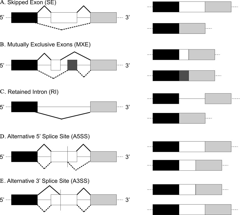
Figure 1A is an alternative splicing depicting skipped exon (S E) splicing. On the left, three exons are displayed in a row linked with introns and splicing outcomes, ranging between 5 to 3 splice sites. On the right, three exons are displayed in a row. Figure 1B is an alternative splicing depicting Mutually exclusive exons (M X E). On the left, three exons are displayed in a row linked with introns and splicing outcomes, ranging between 5 to 3 splice sites. On the right, three exons are displayed in a row. Figure 1C is an alternative splicing depicting Retained intron (R I). On the left, three exons are displayed in a row linked with introns, ranging between 5 to 3 splice sites. On the right, three exons are displayed in a row. Figure 1D is an alternative splicing depicting Alternative 5′ splice site (A 5 S S). On the left, three exons are displayed in a row linked with introns and splicing outcomes, ranging between 5 to 3 splice sites. On the right, three exons are displayed in a row. Figure 1E is an alternative splicing depicting Alternative 3′ splice site (A 3 S S). On the left, three exons are displayed in a row linked with introns and splicing outcomes, ranging between 5 to 3 splice sites. On the right, three exons are displayed in a row.

Most common types of alternative splicing. Exons are shown in rectangles, and introns as lines. The products of the splicing process are shown on the right. Black and dotted lines indicate differential splicing outcomes. Adapted with permission from Dlamini et al. (2017). Note: A3′SS, alternative 3′ splice site; A5′SS, alternative 5′ splice site; MXE, mutually exclusive exon; RI, retained intron; SE, skipped exon.