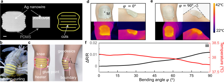
Fig. 8. Dynamically conformable biomimetic heater.
a Photograph of the 2D precursor. Scale bar: 10 mm. The right shows the schematics of the cross-section of the AgNW/PDMS heater and the cut pattern. b, c Schematics of the heater mimicking the shell of the Mantis shrimp composed of geodesics attached to the human knee. b Curling shell of the Mantis shrimp. Yellow lines represent geodesics. c Schematic of the heater attached to the knee. Pink and yellow lines are the boundary and the geodesics, respectively. Red dots are the points with the adhesive. Black dashed lines representing the geodesics are perpendicular to the boundary with the knee bending. d, e The kirigami heater deforms with the knee as the knee bends from 0° (d) to 90° (e) and the corresponding thermal image upon heating. φ denotes the bending angle of the knee. M is the center of the knee. The color bar represents the temperature. f Electric resistance of the heater and the temperature of the point M as a function of the bending angle φ.

