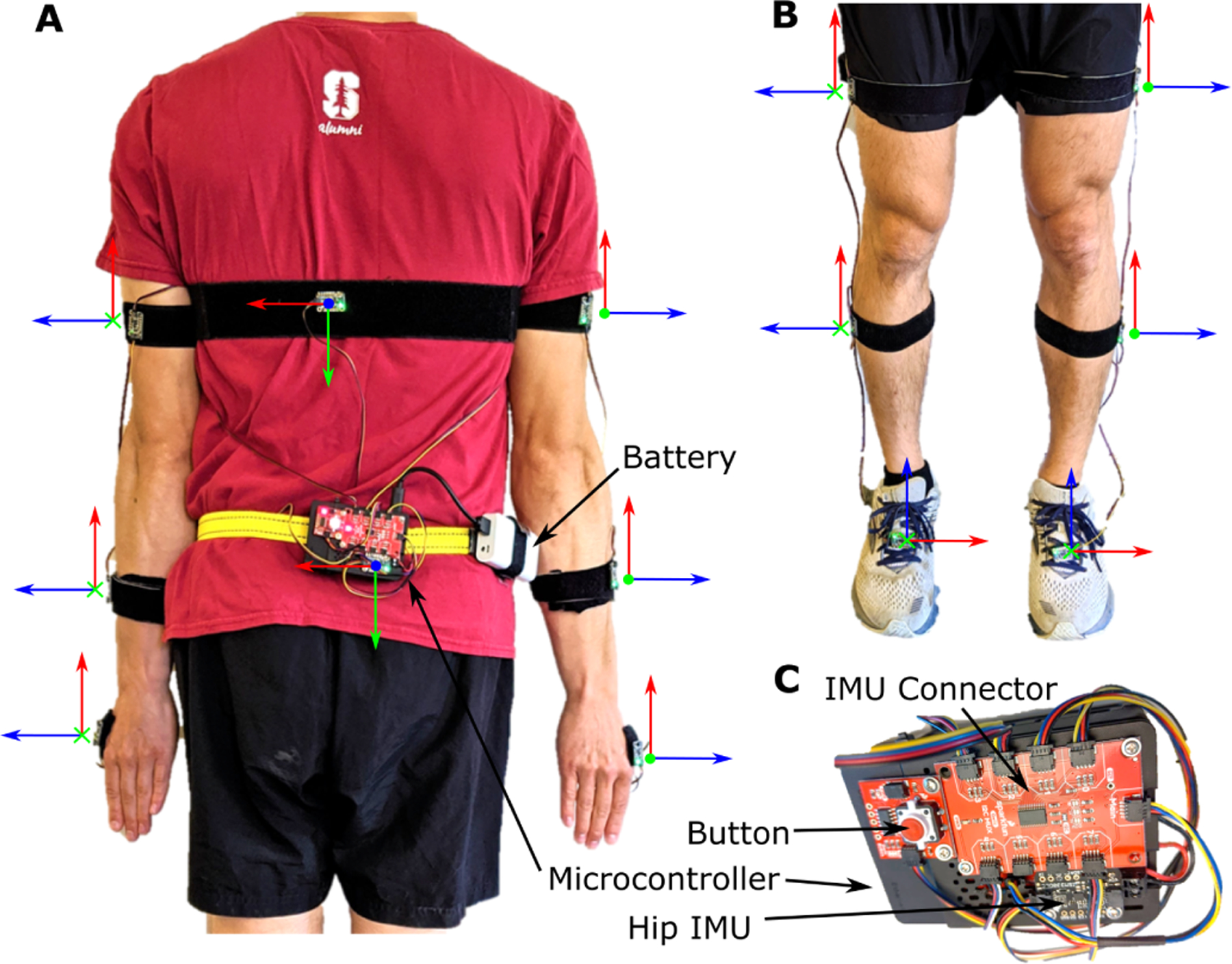
Fig. 1.

The components and default IMU orientations of the OpenSenseRT System. (A) An IMU on the pelvis is required and acts as the base in order to compute the relative orientation of other sensors. The OpenSenseRT System accommodates a variable number of additional IMUs to customize which kinematics are measured. To monitor movement of the upper body, three IMUs may be placed on each arm (on the upper arm, forearm, and hand). An additional IMU can be placed on the torso. The orientation frame with axes shown in red, green, and blue is used to orient the x, y, and z axes defined on each IMU. These individual body frames should align with the world reference frames of the fore-aft, mediolateral, and vertical axes, while the subject’s joint segments are aligned in a neutral standing (or other known) position. (B) The lower-limb IMU placements also require the pelvis IMU as a base and can include up to three IMUs on the thigh, shank, and foot of each leg. OpenSenseRT allows for 1 to 14 of these IMUs to be sampled in a custom configuration. (C) A zoomed in view of the system components shows the microcontroller, battery, button (for starting and stopping recordings), IMU connector, and pelvis IMU.
