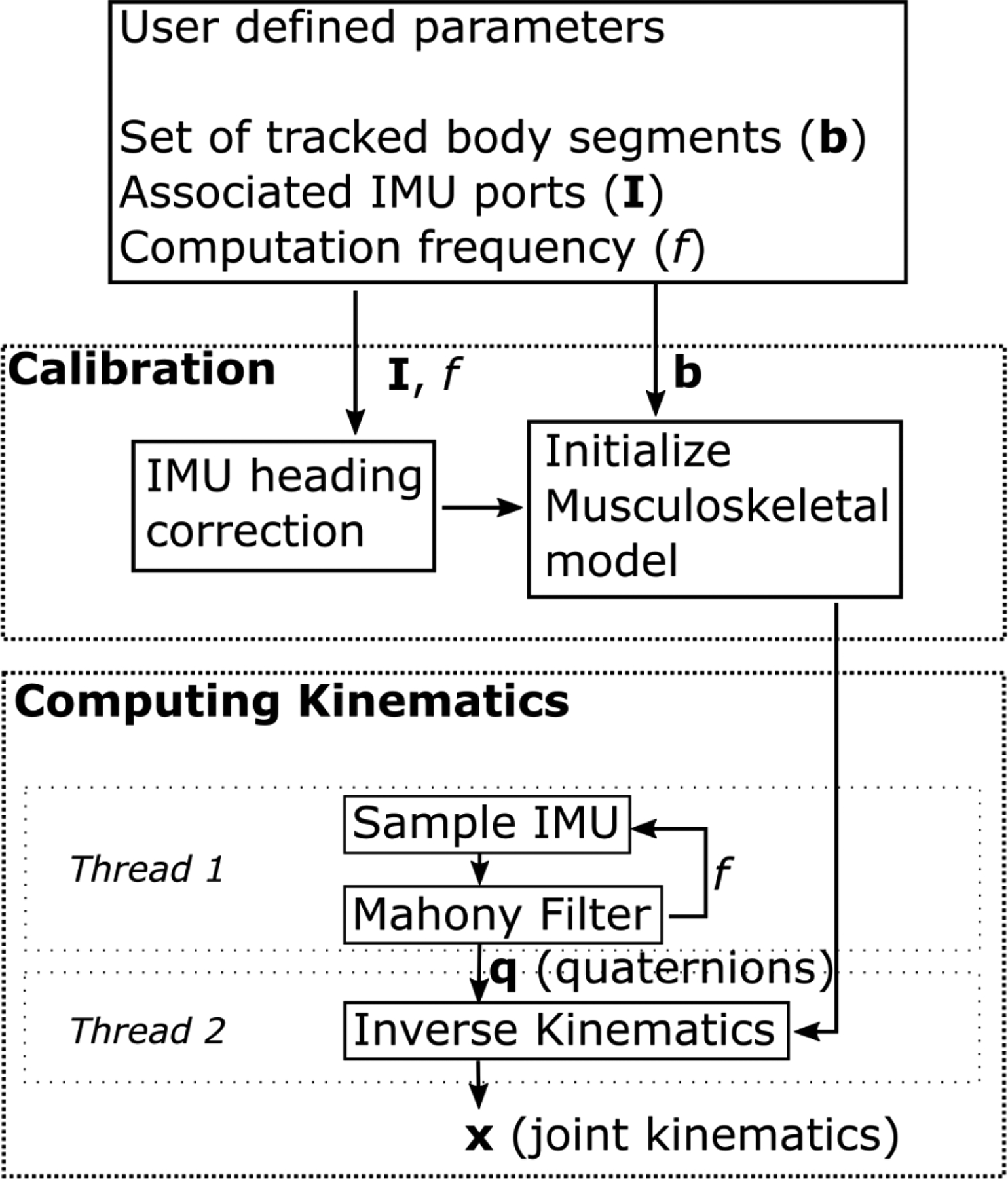
Fig. 2.

Flowchart for computing joint kinematics. The user defines the set of body segments to track, the IMU ports associated with the segments, and the computation frequency. The calibration process consists of a heading correction for the given IMUs and initializing the pose of the musculoskeletal model. The calibrated model and initial pose are passed to the inverse kinematics solver. One thread on the microcontroller records raw IMU data and computes orientations for each body segment using a Mahony Filter at each step. A second thread takes these orientations and the musculoskeletal model to solve the inverse kinematics, estimating joint kinematics at each time step.
