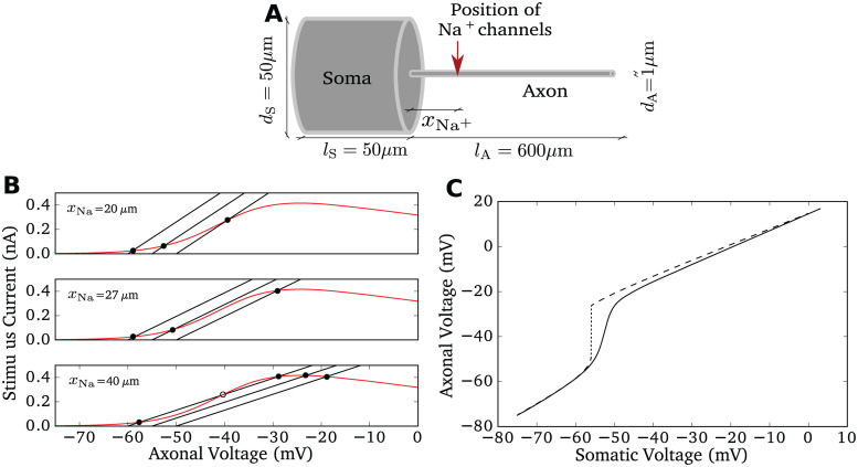
Fig 1. Model properties.
A Sketch of the model morphology: soma and axon are modeled as cylinders. The sodium conductance is positioned at xNa and the stimulus current is injected at the middle of the soma. For simulation and model details see Methods. B Bifurcation of axonal voltage, replicating Fig 2 of [31]. Sodium current (red) and lateral currents (black, with somatic voltage fixed at −60mV, −55mV, −50mV respectively) are plotted as a function of axonal voltage at different xNa. The intersection points between the black curve and the red curve indicate stationary axonal voltage given the somatic voltage. For large xNa = 40μm, the first intersection point changes discontinuously for increasing somatic voltage. C Axonal voltage plotted against somatic voltage for two conditions with xNa = 40μm. Only when the somatic voltage is artificially fixed to a slowly increasing potential (dashed), a sudden jump in the axonal voltage occurs (dotted), when the voltage control of the axonal voltage is lost around −55mV. In a dynamic situation, here a current clamp with injection of a constant current driving firing at 5 Hz, this jump disappears (solid line), the transition is more gradual.

