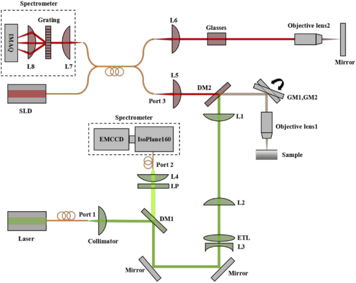
Fig. 1.
Schematic of the experimental setup. DM1, DM2: Dichroic Mirror; ETL: Electrically Tunable Lens; L1, L2, L3, L4, L5, L6, L7, L8: Lens; GM1, GM2: Galvo Mirror; LP: Long Pass Filter; SLD: Super Luminescent Diode; EMCCD: Electron Multiplying Charge Coupled Device Camera; IMAQ: Image Acquisition System; Port 1 is for Raman excitation, Port 2 is for Raman collection, and Port3 is for OCT sampling arm.

