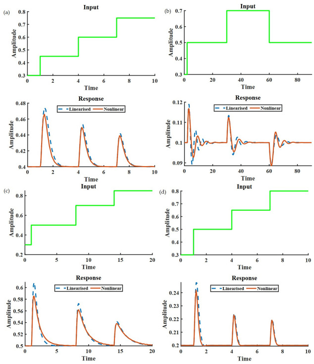
Fig 4.
(a) shows the response of the output node for a three-node IFFLP topology. (b) shows the same for a three-node NFBLB. The oscillatory behavior can be attributed to the complex eigenvalues of the A. Similarly, (c) shows a non-oscillatory response of an NFBLB motif. (d) is the response of the output node of a network containing both the admissible network structure i. e. incoherent feedforward path and negative feedback. The network architecture and necessary values for this simulation have been provided in S1 Text.

