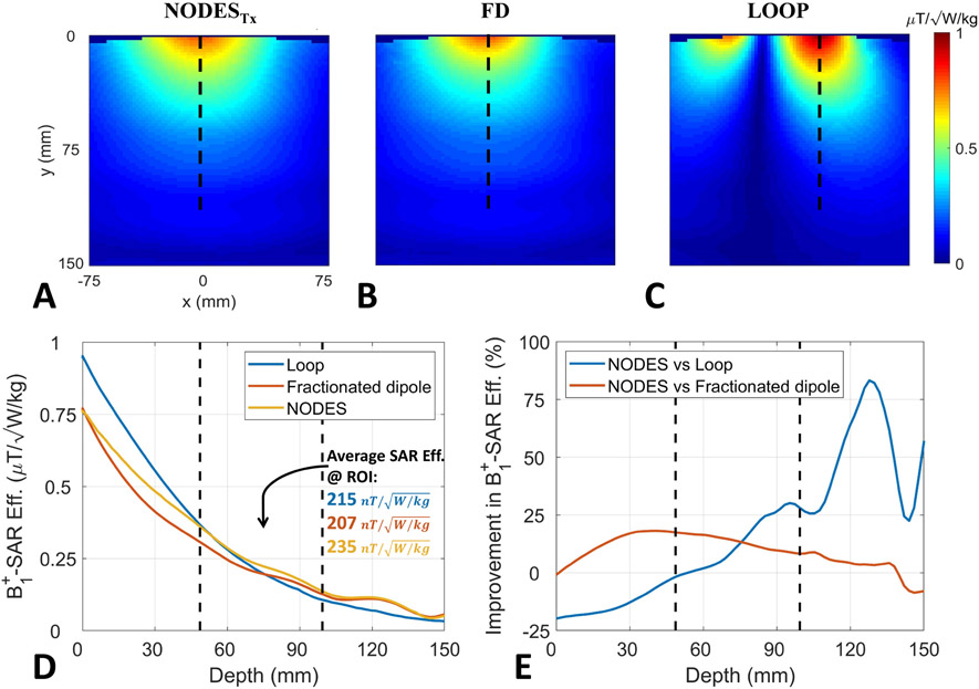
Figure 7.
B1+-SAR efficiency comparison. Axial B1+-SAR efficiency map of (A) NODESTx antenna, (B) fractionated dipole, and (C) loop coil. The vertical dashed lines in (A-C) show the location of the profiles used in (D-E). (D) B1+-SAR efficiencies of the three structures with increasing distance from the element. (E) Improvement of B1+-SAR efficiency with increasing distance achieved by the NODESTx compared to the fractionated dipole and loop. The vertical dashed lines in (D-E) indicate the start and end ranges over which the NODESTx were optimized and represent the approximate depth of the anatomy of interest (i.e. the spine).

