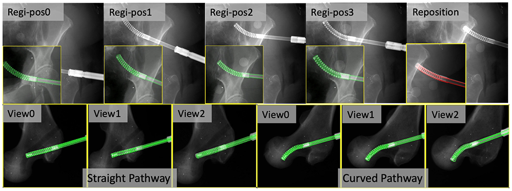
Fig. 12.

2D overlay examples of fluoroscopic images (background) and DRR-derived edges in green when registration is converged. Top: Cadaveric Specimen1 CM registration results and position overlay after reposition (in red). The original full size image is placed at background and the cropped CM registration image is placed at foreground lower left corner. Bottom: Cadaveric Specimen2 CM registration results of each C-arm view for the straight and curved pathway insertions.
