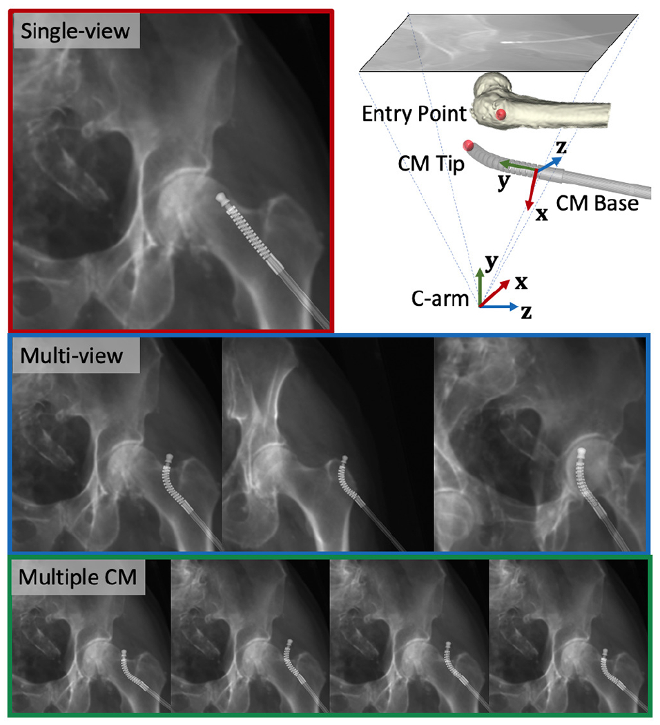
Fig. 8.

Example of simulation images. Red: single-view image. Blue: multi-view images. Green: Multiple CM pose images. Upper right: CM base and C-arm coordinate frames used to report the registration error are marked with RGB cross arrows using an example projection geometry. The femur entry point and the CM tip point are marked using red spheres.
