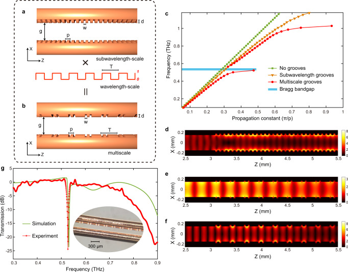
Fig. 1. Direct engraving of Bragg gratings on metal-wires.
Based on a two-wire waveguide (TWWG) geometry (with a wire radius r = 127 µm and an air gap g = 300 µm), Bragg gratings are realized by directly engraving grooves with multiscale structures (150-periods-long) along the metal-wires. a Schematic of the TWWG with sub-λ periodic grooves. Geometry of the grooves: width w = 35 µm, depth d = 40 µm, and period p = 80 µm. b Schematic of the TWWG with multiscale grooves. This structure is achieved by superimposing a wavelength-scale periodic modulation with period T = 280 µm onto the sub-λ periodic grooves shown in (a). c Simulated dispersion relations for the plain TWWG (no grooves) and the TWWGs with sub-λ and multiscale grooves. d Simulated electric field modulus distributions, evaluated at 1.2 THz, in the TWWG with sub-λ grooves, showing that the THz energy is mainly trapped within the grooves, preventing further propagation. Simulated electric field modulus distributions in the TWWG with multiscale grooves evaluated at 0.53 THz (e) and at 1.0 THz (f), respectively. g Simulated and experimental transmission spectra of the TWWG with the integrated Bragg gratings. The experimental result is obtained via a standard THz time-domain spectroscopy (TDS) system. The transmission spectra are achieved by calculating the ratio between the power spectra of the signals propagating through the TWWGs with and without grooves. The inset shows the optical microscopic image of the Bragg gratings directly etched on one of the two wires.

