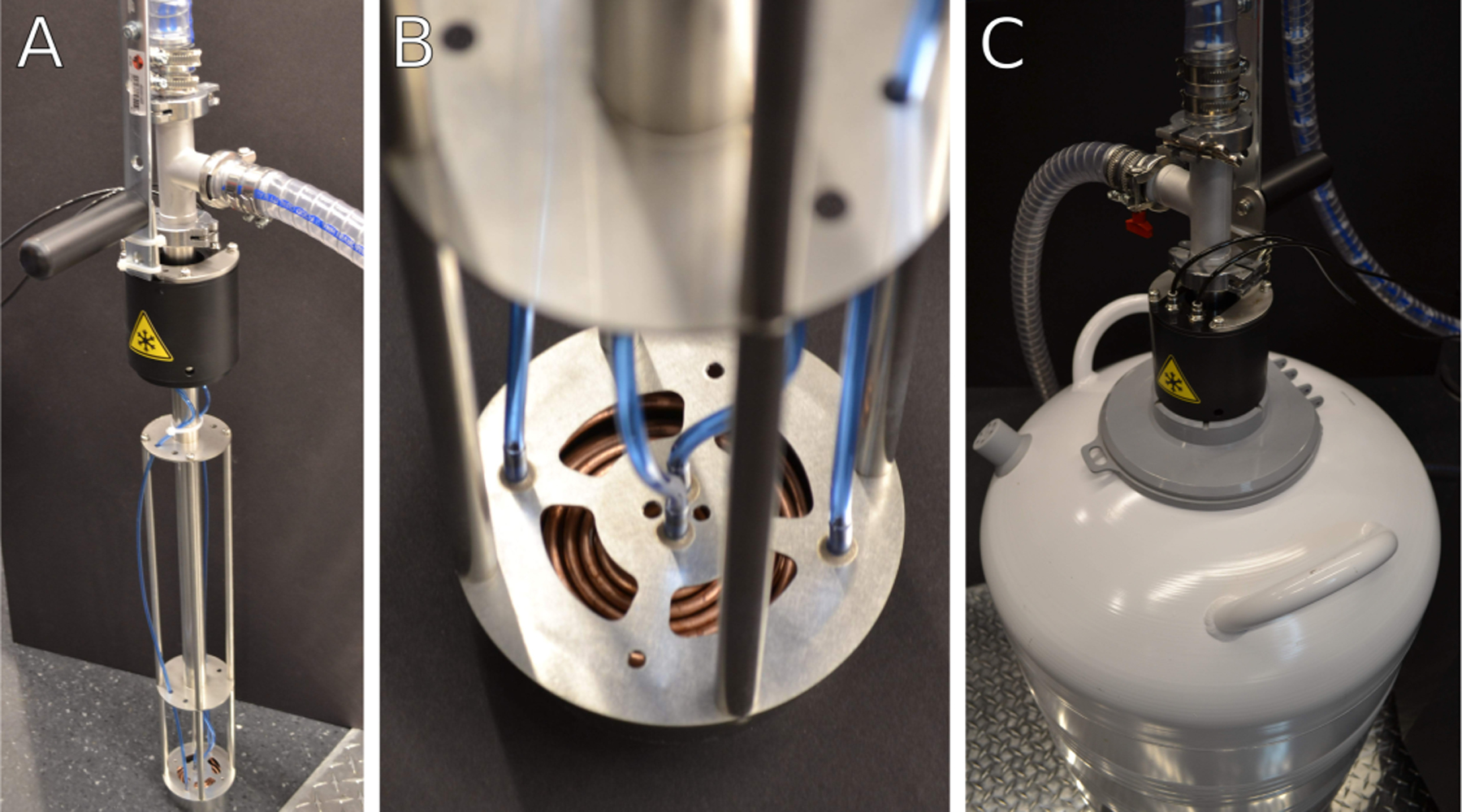
Figure 4: Heat exchanger assembly.

(A) Heat exchanger in a stand when not in use. During cryogenic operation, the heat exchanger assembly is immersed into a liquid nitrogen dewar. The heat exchanger assembly is kept under partial vacuum through the clear tubing attached near the top to maintain thermal isolation of cold gas nitrogen. (B) Detail of heat exchanger coils and nitrogen gas lines. Warm nitrogen gas is passed from the blue gas lines into the copper coils and cooled to liquid nitrogen temperatures. Cold gas is routed through the body of the heat exchanger into the microscope stage. (C) Image of heat exchanger assembly inserted into a liquid nitrogen container during cryogenic operation. The thick clear tubing near the top of the heat exchanger unit is part of the vacuum isolation system.
