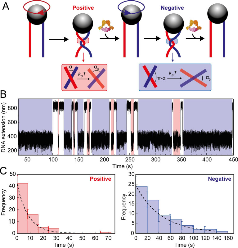
Figure 7. Topo VI unlinking single DNA crossings.
(A) Single crossing assay schematic with DNA crossing geometry for positive (left-handed, red) and negative (right-handed, blue) DNA writhe. One 360° clockwise magnet rotation imparts a positive crossing, which is unlinked by topo VI, followed by the generation and subsequent topo VI-dependent unlinking of a negative DNA crossing, formed by a 360° anticlockwise magnet rotation. The crossing angle is defined as the clockwise angle between the top and bottom DNA strands. For positive crossings this is an acute angle (α); for negative crossings the obtuse angle is the supplement (π-α) of the positive angle. For topo VI, achieving the preferred angle (α0 < 90) requires a smaller thermal fluctuation of positive crossings, therefore there is a higher probability of α0 being achieved than for negative crossings. (B) Single crossing unlinking data, collected for a braid formed from 3 kb DNA tethers, spaced 624 nm apart, at a force of 1 pN, using 0.9 nM topo VI and 1 mM ATP. Positive crossings (red) were relaxed more rapidly than negative crossings (blue). (C) Distributions of the topo VI-dependent unlinking times for negative (blue bars) and positive (red bars) crossings, of the data shown in B. The data were fitted with single exponentials, P(t) = τ–1exp(-t/τ), returning characteristic unlinking times of τR = 47 ± 7 s for negative crossings, and τL = 8 ± 1 s for positive crossings, giving a ratio of τL/ τR = 0.19 ± 0.04.


