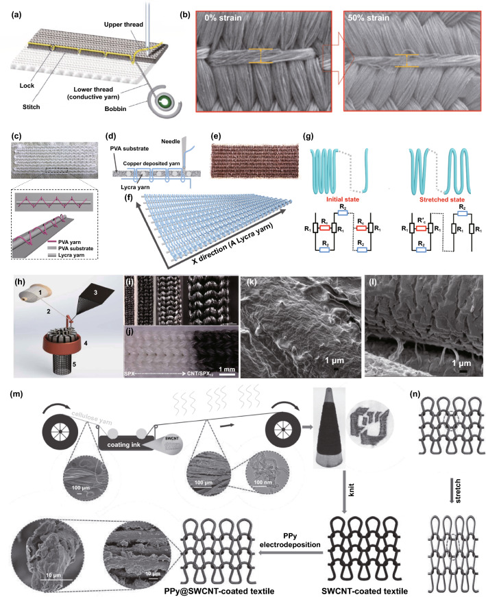
Fig. 8.
a Illustration of locking conductive yarns over a textile substrate to fabricate strain sensors, and b the surface morphologies of the strain sensor under 0 and 50% strain respectively [180]. Copyright © 2019 Wiley–VCH. c A rectangular Lycra track fixed onto PVAT substrate by PVAT yarn, and d the diagram of embroidering copper deposited yarn in the Lycra track via lock-stitch embroidery to fabric strain sensors. e The photo of the embroidery pattern with copper deposited yarn and the Lycra track. f The embroidering sensor after dissolving PVAT substrate. g The sensing networks and resistance models of the embroidery sensor under initial and stretched states respectively [6]. Copyright © 2021 Wiley–VCH. h Illustration of fabricating a knitted Spandex/CNT strain sensor through a circular knitting machine, i, j different-structure Spandex/CNT sensors showing the pattern flexibility of the technique, k the surface CNT on the pristine Spandex fibers, and l the CNT cracks on the stretched Spandex fibers to showing the sensing mechanism [188]. Copyright © 2016 American Chemical Society. m The process of producing a knitting strain sensor through coating CNT and PPy on cellulosic yarns, and n the schematic diagrams of the sensor without and with elongation, showing the mechanism of the sensor can be attributed to geometry effects [189]. Copyright © 2016 Wiley–VCH

