Figure 2.

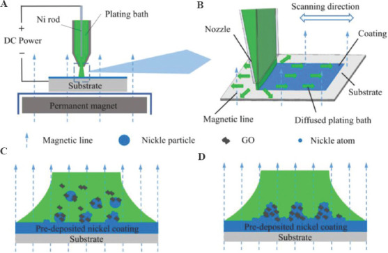
(A) Schematic diagram of experimental equipment. (B) The process of composite coating. (C-D) Model of introducing GO into the coating.

(A) Schematic diagram of experimental equipment. (B) The process of composite coating. (C-D) Model of introducing GO into the coating.