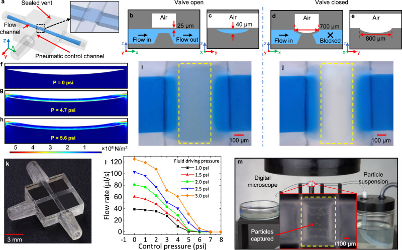
Fig. 4. 3D-printed microfluidic valve and specimen platform for automation.
a CAD model showing the configuration of the 3D-printed microfluidic valve. The vent at the end of the control channel will be sealed via construction glass glue after clearing uncured resin. The inset gives the detailed structure of the membrane and the ramp. Schematic diagram showing the front b and side c sectional view of the valve filled with blue-dyed DI water in the open state. Schematic diagram showing the front d and side e sectional view of the valve in the closed state. The liquid cannot pass through. The membrane is fully conformal to the curved ramp surface under pressure. FEA simulation of the valve membrane deflection at different pressures. f 0 psi. g 4.7 psi. h 5.6 psi. The color heat map shows the von Mises stress on the membrane at these pressures. i Microscope image showing the top view of the valve in the open state. j Microscope image showing the top view of the valve in the closed state. The liquid between the ramp and the membrane is displaced. k Fabrication result of the microfluidic valve (isometric view). l Closing pressure test of the fabricated valve under varying fluid driving pressures. m Specimen platform for particle samples observation and measurement. The deflected membrane captures the green particles.

