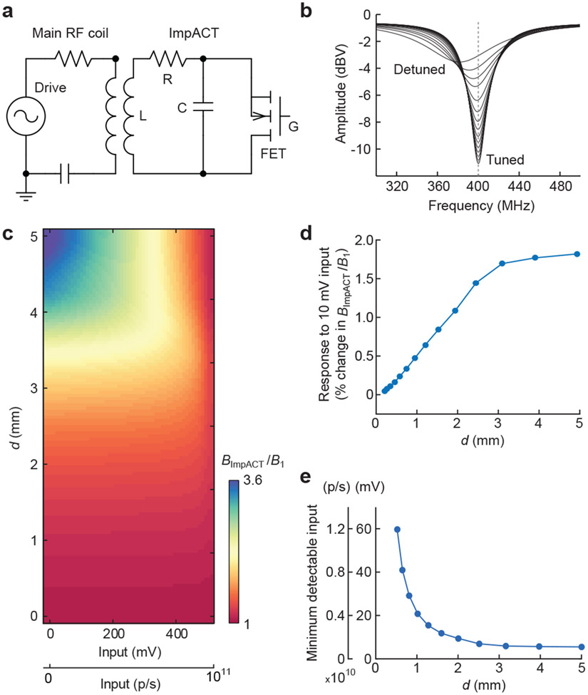
Figure 2. Theoretical performance of ImpACT designs.
(a) Equivalent circuit used for simulation of ImpACT devices (right) coupled to an MRI scanner’s main RF coil (left). RF pulses generated by the scanner drive the ensemble. Resistor (R), inductor (L), and capacitor (C) of the ImpACT are labeled, as is the device’s FET with gate terminal (G). (b) ImpACT tuning curve simulations as a function of voltage input that causes the device to vary between fully tuned and fully detuned states (labeled). (c) Relative enhancement of local RF amplitude as a function of the ImpACT’s inductor diameter (d) and input strength in mV or photons per second (p/s). RF enhancement by the ImpACT is expressed as BImpACT/B1, which translates directly into an increase in flip angle during application of an MRI pulse via the scanner’s main coil. (d) Response to a 10 mV input (also equivalent to 2 x 10⁹ p/s), compared with zero input, as a function of the ImpACT inductor diameter. Changes in BImpACT/B1 of 1% or greater are likely to be detectable in imaging. (e) Minimum photonic and voltaic input signals predicted to produce 1% change or greater in BImpACT/B1, compared with zero input, as a function of device diameter.

