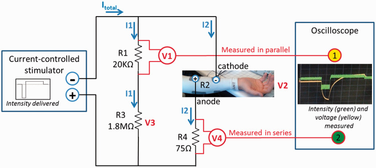
Figure 4.
Diagram of the electrical circuit used to estimate voltage (V2) and intensity (I2) of the stimulations delivered to the electrodes. Channel 1 of the oscilloscope measured and recorded the voltage across R1, a resistor in parallel with the electrodes (V1, to estimate voltage across electrodes). Channel 2 measured the voltage across R4, a resistor in series with the electrodes (V4, to estimate the current amplitude going through the electrodes).

