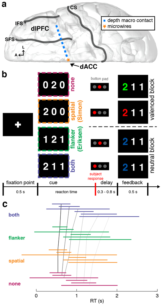
Figure 1. Recording configuration, task description, and behavioral performance |.
a, Diagram of the intracranial implant including a stereotactically placed intra-cerebral depth electrode with macroelectrodes (blue squares) along the shaft from dlPFC to dACC and microwire electrodes (orange star) in dACC. A, anterior; L, lateral; CS, central sulcus; SFS, superior frontal sulcus; IFS, inferior frontal sulcus. b, Multi-source interference task (MSIT). The subject sees a cue consisting of 3 numbers and has to identify the unique number (“target”) and respond with a button push: left button if the target is “1”, middle if “2”, right if “3”. Incongruence between the location of the target number in the 3-digit sequence and location of the correct button in the 3-button pad produces spatial (Simon) conflict (orange). The distracting presence of numbers that are valid button choices (“1”, “2”, “3”, vs. “0”, which is not a valid choice) produces flanker (Eriksen) conflict (green). Trials can also have neither type of conflict (magenta) or both types (violet). In all 4 example trials shown, “2” is the target; thus the middle button is the correct response. Following the response, valenced (green/red for correct/incorrect; 2 example trials shown above dashed line) or unvalenced (blue regardless of correctness; 2 example trials below dashed line) feedback is provided in alternating blocks of 10 trials. c, Line plots of RT distributions across all patient. Each colored line represents two standard deviations of RTs centered on the mean RT and color-coded each conflict condition. Black and gray lines connect the means across conflict conditions within each patient. There was a statistically significant difference among conflict conditions (generalized linear mixed effects model, t3881 = 2.36, p = 0.01). RT distributions for each subject and session are shown in Supplementary Figure 7.

