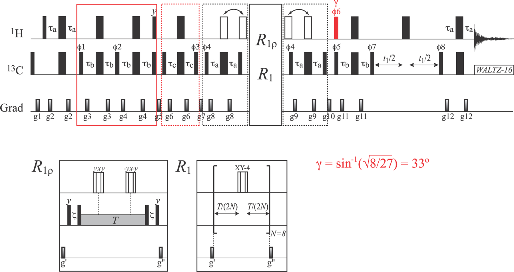
Figure 6.

Pulse scheme for the measurement of the R1ρ and R1 relaxation rates of the inner 13C magnetization mode of the I = 3/2 manifold (L2 ± L3). All the parameters of the scheme (including delays) are the same as in Figure 2. The 1H pulse shown in red is applied with flip angle γ = sin−1(√8/27) = 33°. “Open” 1H 180° pulses of the main scheme (in the elements enclosed in dashed black boxes before and after the relaxation delays) are applied either simultaneously with 13C 180° pulses (for in-phase measurements; L2 + L3) or outside the 2τa elements (for antiphase measurements; L2 − L3) as indicated by arrows above the scheme. “Open” 1H pulses in the R2 and R1 measurements are composites pulses of the 90°–240°–90° variety29 that are applied using the phase-cycling indicated in the figure for the R1ρ measurements, and XY-4 phase-cycling30,31 for R1 measurements. Note that a total of eight 1H π-pulses (N = 8) is used for R1 measurements to avoid artifacts due to fast pulsing. The durations and strengths of pulsed-field gradients (ms; G/cm) are as follows: g1 = (1.0; 25), g2 = (0.4; 15), g3 = (0.3; 20), g4 = (0.35; 25), g5 = (1.4; 12), g6 = (0.2; 20), g7 = (0.8; 20), g8 = (0.5; 20), g9 = (0.4; 20), g10 = (1.0; 20), g11 = (0.3; 12), g12 = (0.5; 15), g′ = (0.8; 25), and g″ = (0.6; 20). The phase cycle is as follows: ϕ1 = 2(x), 2(−x); ϕ2 = x, −x; ϕ3 = 2(x), 2(−x); ϕ4 = 2(x), 2(−x) for antiphase (L2 − L3) measurements and 2(y), 2(−y) for in-phase (L2 + L3) measurements; ϕ5 = x, −x; ϕ6 = 4(x), 4(−x); ϕ7 = y, −y; ϕ8 = x; and receiver phase = (x,−x,−x,x, −x,x,x,−x). Quadrature detection in t1 is achieved via the States32 incrementation of ϕ8.
