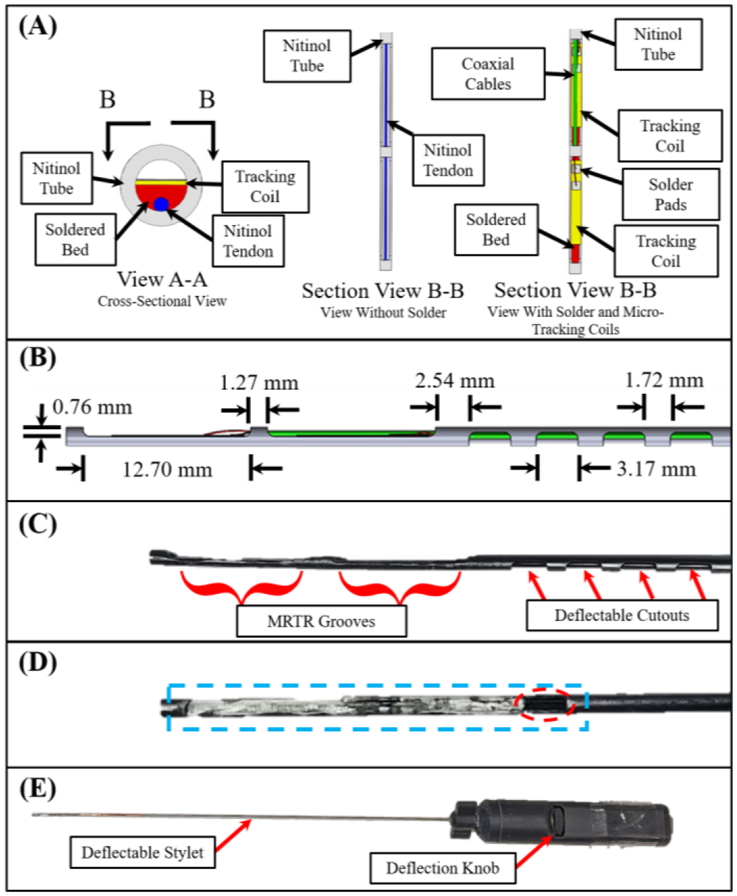
Fig. 2.

View A-A in (A) shows the solder bed (red), the nitinol tendon (blue), the MRTR coils (yellow), and the nitinol tube used as the brachytherapy stylet (grey). Section View B-B provides a downward looking view of the same assembly, without the solder (left), and with the solder, tracking coils, and micro-coaxial cables (right). (B) Side view of the stylet with the corresponding dimensions. (C) The stylet following the machining operations. (D) Stylet after machining the soldered surface flat (blue). Note the gap left to provide access for the micro-coaxial cables (dotted red ellipse). (E) Full handle assembly after assembly.
