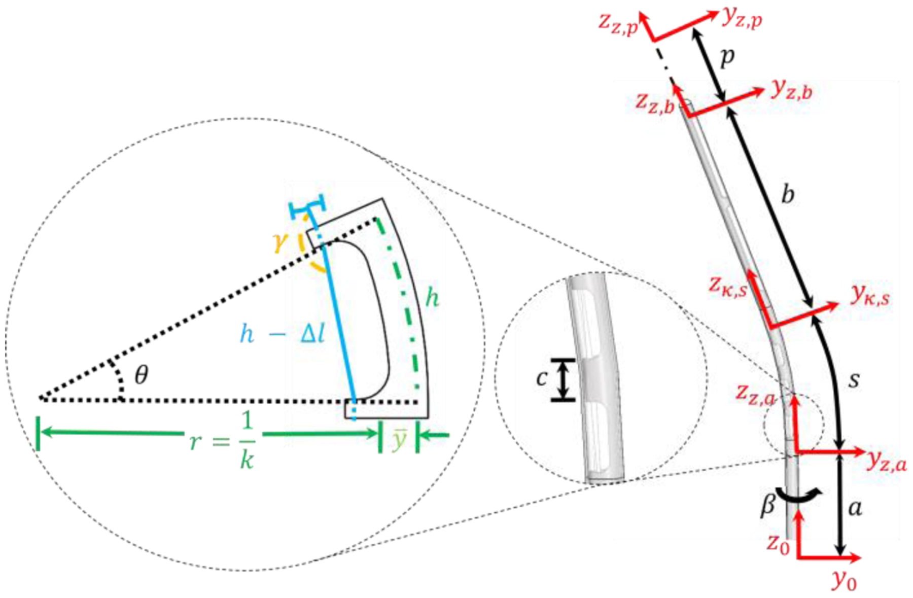
Fig. 3.

A single cutout being deflected and its corresponding geometry is depicted to the left based on tendon retraction. Blue is the tendon, the dashed green line is the location of the neutral bending plane, and the black dashed lines depict the change in the deflection angle. A side view (right) of the stylet is also given. The catheter surrounding the stylet is transparent. Additionally, the location of location coordinate frames can be seen in red.
