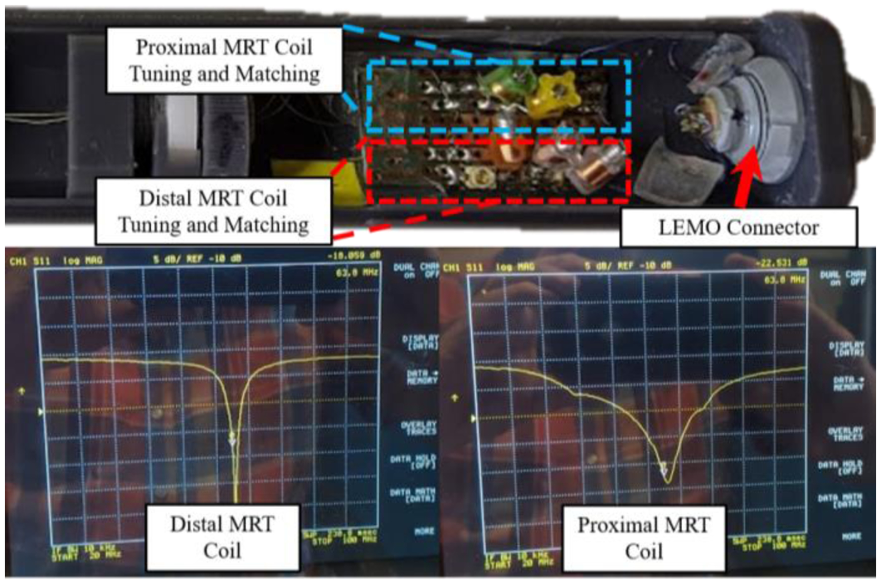
Fig. 4.

The upper image is the proximal end of the handle assembly, which contains the tuning and matching circuits for the proximal and distal MR-Tracking coils. The lower images are the S11 plots of the distal and proximal MRT coils, as seen on a Vector Network Analyzer, after tuning and matching the circuitry. The resonance occurred at 63.8 MHz (the Larmor frequency of the Siemens 1.5T scanner).
