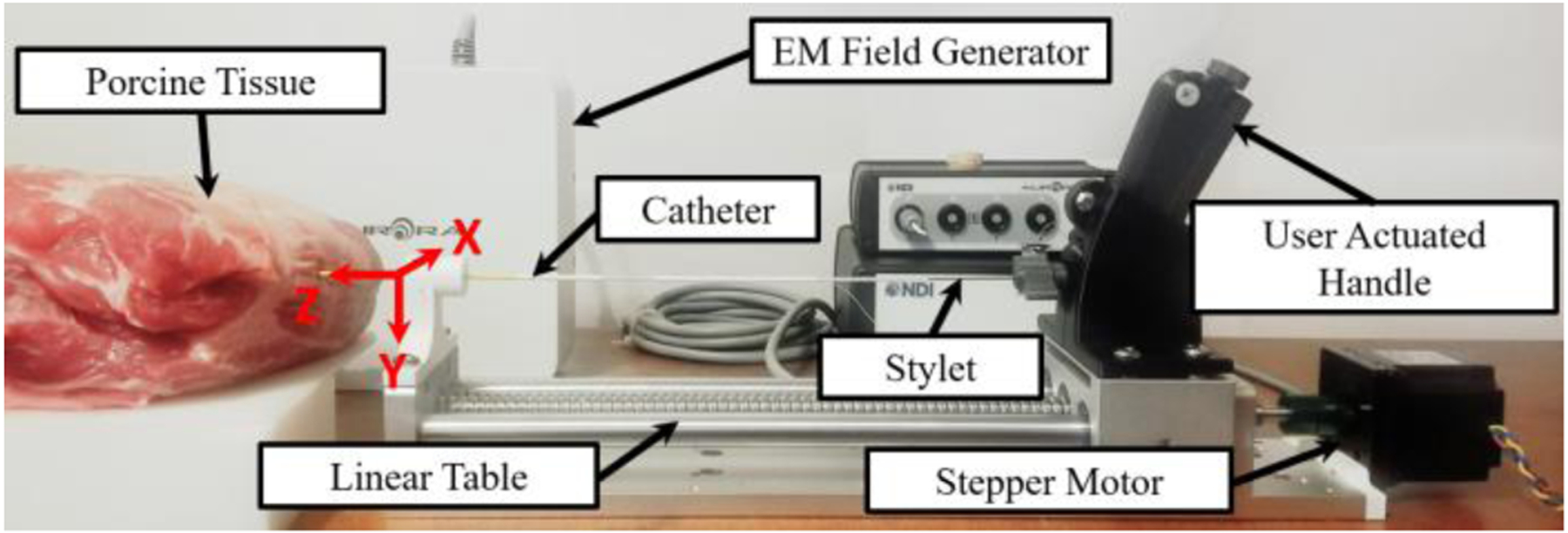
Fig. 7.

The experimental setup for the trajectory test in the porcine tissue is depicted above. The location and orientation of the robot base frame can be seen. The z-axis is in line with the stylet pointing toward the direction of insertion and the y-axis is orientated downwards. The stylet trajectory was obtained with an EM tracker.
