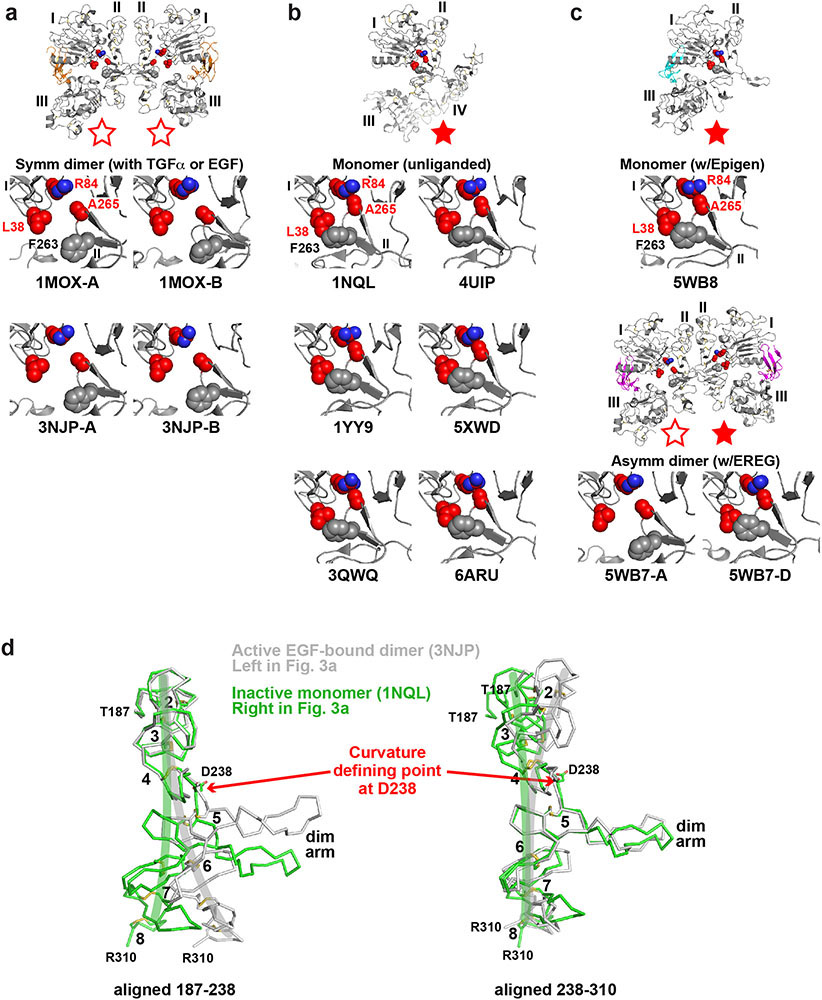
Extended Data Fig. 6. Autoinhibitory domain I/II interactions in different sEGFR structures.
a. As expected for autoinhibitory interactions, R84/A265 and L38/F263 interactions are broken in ‘active’ symmetric dimers of sEGFR induced upon activation with TGFα (1MOX15) or EGF (3NJP14,17). This configuration is represented by open red stars, as in Fig. 3.
b. Disposition of key GBM-mutated residues (L38, R84 and A265, coloured red) for comparison in ‘inactive’ configurations of the EGFR extracellular region. The positions of these side-chains are shown in monomeric tethered forms of sEGFR59-63. In each case, the R84 side-chain directly contacts that of A265, and the L38 side-chain is in van der Waal’s contact with that of F263 (grey spheres: not mutated in GBM). These represent autoinhibitory interactions between domains I and II as described in the text and pointed out in our previous studies64. This configuration is represented as a filled red star.
c. Importantly, the autoinhibitory R84/A265 and L38/F263 interactions are also retained in the ligand-bound monomer seen observed when EPGN binds to sEGFRWT (5WB85). Moreover, as shown in the lower two panels, these autoinhibitory interactions are retained in the right-hand molecule of the asymmetric EREG-induced dimer of sEGFRWT (5WB7: Fig. 3a) – see filled red star – but are lost in the left-hand molecule (open red star).
d. Comparison of the ‘bend’ in domain II in inactive monomeric forms of sEGFR (light green) and active dimeric forms (grey) – colours corresponding to those used for sEGFR chains in Fig. 3a. The structures of unliganded monomeric sEGFR (PDBID: 1NQL59) and an EGF-induced WT sEGFR dimer (PDBID: 3NJP14) were used. Only residues 187-310 of domain II are shown. In the left-hand panel, the two structures are overlaid using residues 187-238 as reference. In the right-hand panel, residues 238-310 are used as reference. This analysis reveals that the two structures differ by a bend at residue D238 (marked as ‘Curvature defining point’). The approximate direction of curvature is shown by green and grey brush strokes on each structure. The dimer arm is labelled, as are disulphide-bonded modules 2-8 of domain II59. This figure is based on one by Ferguson16.

