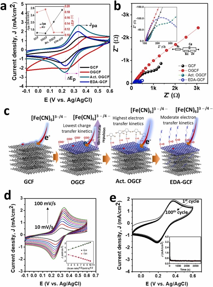
Fig. 5.
(a) CVs (scan rate: 100 mV/s) (inset shows the plots of the summary of Jpa and ΔEp) and (b) Nyquist plots (inset shows the magnified Nyquist plots) of GCF, OGCF, Act. OGCF, and EDA-GCF electrodes. (c) Schematic of the GCF modification and electron transport of the various electrodes. (d) CVs of EDA-GCF electrodes in [Fe(CN)6]3−/4− redox electrolyte solution at different scan rates (10, 20, 30, 40, 50, 60, 70, 80, 90, and 100 mV/s) and (e) consecutive CVs (100 cycles) of the EDA-GCF electrodes in [Fe(CN)6]3−/4− redox electrolyte solution at a scan rate of 100 mV/s (inset shows the CA plot of the EDA-GCF electrodes in [Fe(CN)6]3−/4− redox electrolyte solution at 0.335 V).

