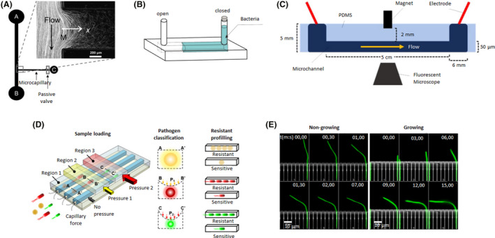
Fig. 1.

Microfluidic device designs of individual and linear channels. A. The bacterial flow travelled from reservoir A to B, whereas, chemoattractants were added to reservoir C. A fraction of the bacterial population swam into the capillary where chemotaxis was studied. Adapted from (Ahmed and Stocker, 2008). B. An oxygen gradient was generated by capturing an air bubble on one of the ends of the channel. The opposite end was filled with a bacterial solution. Adapted from (Stricker et al., 2019). C. A magnet was incorporated in the middle of the microfluidic device to attract magnetotactic bacteria that flowed through the channel. Adapted from (Miller et al., 2019). D. A microfluidic device with different regions where pressure could be applied. Depending on the pressure exerted, the channels contracted to different sizes and were able to trap bacteria as a function of their size and shape. Three different bacteria (yellow, red and green) were trapped in regions 1, 2 or 3 (with increasing pressure from 1 to 3). Then, antibiotics were added to examine drug resistance and determine if they were resistant or sensitive. Adapted from (Li et al., 2019). E. A microfluidic device with a side chamber of the same size as the E. coli body trapped single bacteria while their flagellum remained freely mobile in the central channel. Hydrodynamic forces were applied to non‐growing and growing bacteria (green) to determine their bending force and filament deformation at different times (mm, ss: 00,00–15,00). Adapted from (Caspi, 2014). All figure panels were reproduced/adapted with permission from the corresponding publisher and/or journal. Credits for these figures are provided in the References section of the manuscript.
