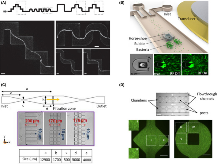
Fig. 7.

Topographic microfluidic devices with irregular shapes.
A. A single‐channel microfluidic device with a streamer shape to examine the formation of biofilms in contact with sharp and rounded corners. Images were taken in the middle horizontal plane after 12 h of a constant flow of 0.75 µm/min (from left to right). Scale bars correspond to 100 µm. Taken from Rusconi et al. (2010). B. A horseshoe shape was printed on the middle of the channel to create a vertical flow in which bacteria were trapped, developing biofilms. The trapped bubble oscillated with an amplitude of ɛRb and a diameter of 2Rb. The vortices were generated by the application of a 1.9 µm radio frequency (RF) signal. Green microbeads were used to track trajectories when the transducer was off and of (RF Off/RF On). Adapted from (Yazdi and Ardekani, 2012). C. A linear device with a filtration zone in the centre of the channel with different geometries and distributions of rectangular and square posts. Bacteria were forced to pass through the filtration zone in the direction of the yellow arrow as a recreation of filtration processes. Adapted from (Marty et al., 2014). D. A microfluidic device with geometrical chambers that may include central posts was designed to determine bacterial organization depending on chamber shape. The flow ran through the flowthrough channels in the direction of the white arrows. Bacteria were oriented 90° regions I, II, IV and V and 45° in region III with respect to the x‐axis. Scale bars correspond to 50 µm. Adapted from (Cho et al., 2007). All figure panels were reproduced/adapted with permission from the corresponding publisher and/or journal. Credits for these figures are provided in the References section of the manuscript.
