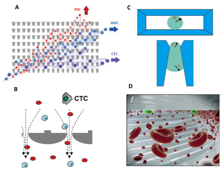
Figure 3.
Microfiltration separation technologies. (A) Microfluidic ratchets for continuous CTC separation. Whole blood is infused from the bottom-left corner of the funnel array and cells travel in a zigzag diagonal path until they reach a blocking funnel row, where they proceed horizontally toward the outlet reservoirs. The size of funnel constrictions is gradually reduced from the bottom row to the top row within the 2D array. Reprinted from [29] with permission (http://creativecommons.org/licenses/by/4.0/) (Accessed on 26 October 2021). (B) Circular microcavity array (MCA) filter. The size of the microcavities was optimized in order to trap CTCs on the microcavities while letting blood cells flow through the filter. Reprinted with permission from [44]. Copyright 2010 American Chemical Society. (C) Pyramidal MCA filter. Top view and vertical section of cell retention in a pyramidal MCA. RT and RL are, respectively, the radius of the curvature of the trailing and leading edges of the cell. Reprinted from [34], copyright 2019, with permission from Elsevier. (D) The Parsortix™ system. Blood is forced along a series of channels with a cross-sectional gap that gradually decreases the dimension of the fluid path and retains CTCs based on their deformable nature and size. Reprinted with permission from [41] under the Creative Commons CC-BY-NC-ND license.

