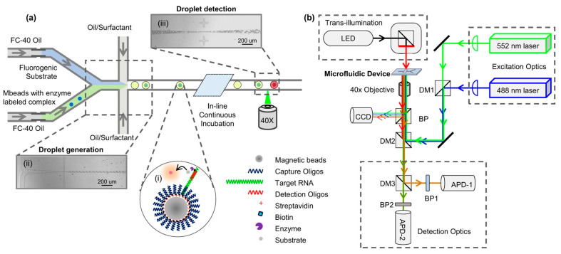
Figure 1.
Transillumination imaging of a microfluidic device. Panel (a) represents a schematic of the microfluidic device used by Guan et al. Panel (b) demonstrates the traditional setup of transillumination imaging where the LED is used as the light source and a microscopic objective lens and a CCD detector on the other side of the microfluidic device that is being imaged. Reproduced from [19] under Creative Commons Attribution 4.0 License.

