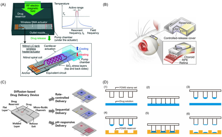
Figure 3.
(A) Schematic diagram of wireless implantable magnetic driven DDSs and its working principle. (B) Working diagram of dual-drug delivery system. (C) The “reservoir-microfluidic channel” system optimization and drug release diagram. (D) Schematic diagram of the wet μCP system manufacturing: (1) PDMS stamp set and drug solution, (2) tip contact with drug solution, (3) drug coated stamps, (4) The position of drug coated stamp above PDMS reservoir, (5) stamp contact on a target surface and (6) final drug loading formation. (A) Jeffrey Fong et al. [80]; (B) Nobuhiro et al. [82]; (C) Yang et al. [84]; (D) Lee et al. [85].

