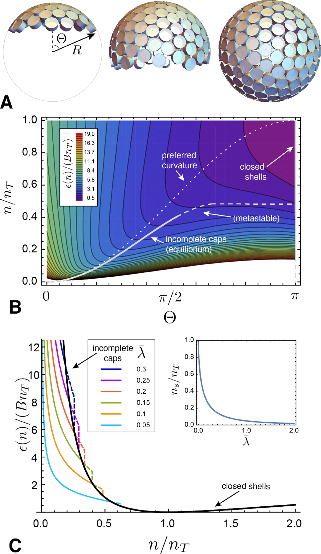
FIG. 9.

(A) Schematic geometry of a “fluid capsule” of tapered subunits, which assumes partial shell geometries of spherical caps with aperture angle 0 < Θ ≤ π. (B) A contour map of the energy density landscape of the capsule model as a function of aperture angle and the ratio of subunits n to the preferred number in the ideal closed shell nT. Low (high) values of ϵ(n) appear as purple (red). The dotted line shows a partial shell with the target curvature, while the solid line indicates the minimal energy cap, whose curvature radius is slightly compressed by the line tension of the boundary. Beyond a threshold cap size n = nS ≃ 0.4nT, this open cap becomes unstable to preclosure, and the minimal energy branch runs along Θ → π. This landscape corresponds to a dimensionless line tension . (C) Plots of the minimal energy branches of assembly: incomplete caps are shown as colored curves (metastable portions are dashed), and the closed shell (Θ → π) is shown as a black curve. The inset shows the size nS corresponding to the preclosure, or “snap”, transition between stable open caps and closed shells as a function of line tension.
