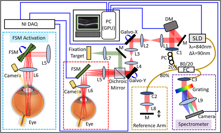
Fig. 1.
Schematic diagram of the VD-OCT system. The purple dashed box on the bottom right corner illustrates the spectrometer combined with a 2048-pixel camera. The dark-yellow dashed box on the bottom center shows the schematic of the reference arm. The red dashed box on the bottom center illustrates the regular OCT galvanometer scanning system. The cyan dashed box on the bottom left corner demonstrates the VD-OCT system when both the galvanometer scanner and FSM are activated synchronously. The red dot lines represent the beam envelope with different scanning angle configurations of FSM. SLD: superluminescent diode; M: mirror; DM: deformable mirror; L1-L9: lens; C1-C3: collimator; Galvo-X/Galvo-Y: the fast/slow axis of galvanometer scanner; FSM: fast steering mirror; NI DAQ: multifunctional data acquisition and control card; PC: polarization controller; FC: fiber coupler; GPU: graphics processing unit.

