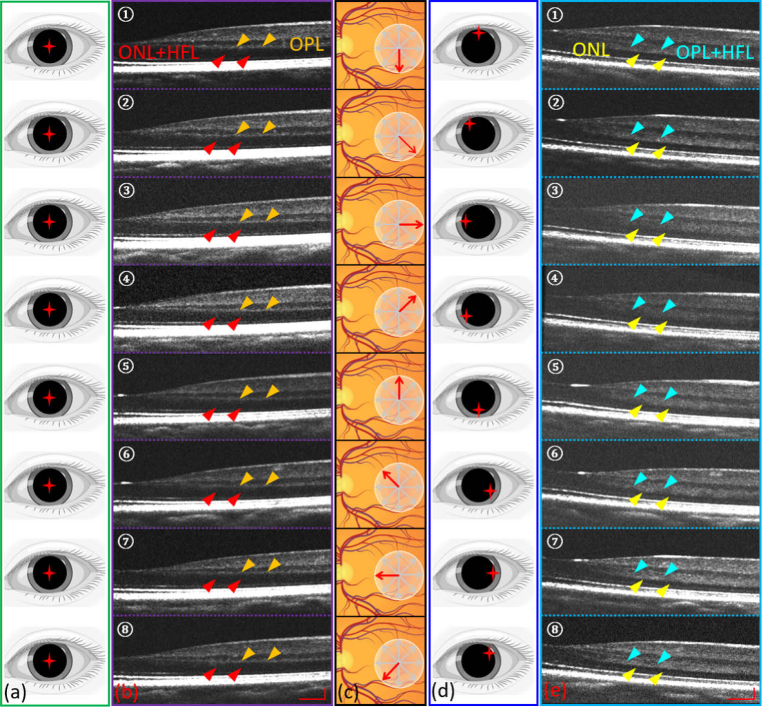
Fig. 5.
(a) Incident beam entry positions in the regular spoke scanning pattern. (b) Eight selected cross-sectional scans (every 45° interval in a scanning cycle) acquired by the regular spoke scanning pattern. Red arrows indicate the combined layers of ONL and HFL. Orange arrows indicate the OPL. (c) Illustration of retinal spoke scan. (d) Corresponding incident beam entry positions in the spoke-circular scanning pattern. (e) Eight selected cross-sectional scans (every 45° interval in a scanning cycle) acquired by the spoke-circular scanning pattern. Yellow arrows indicate the ONL. Cyan arrows indicate the combined layers of OPL and HFL. Scale bars in (b) and (e) are 300 µm (horizontally) and 100 µm (vertically).

