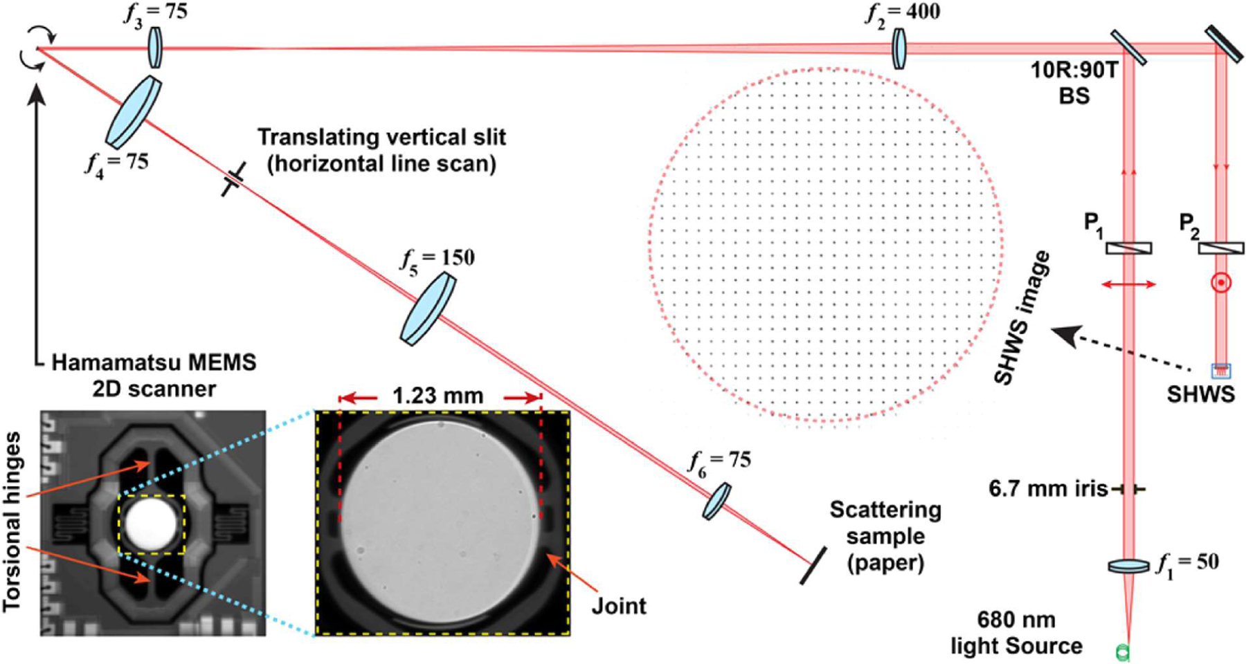
Fig. 2.

Testbed used for measuring dynamic wavefront distortion in a MEMS resonant scanner. In this diagram, BS is a beam splitter, fi represents focal length of an achromatic lens in millimeters, and Pj denotes a linear polarizer. A red dotted line shows a 1.2 mm pupil over a SHWS image. The bottom left panels show the mirror in its mount and a magnified inset.
