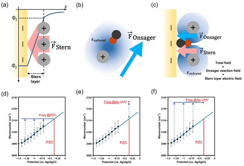
Figure 1.
(a) Diagram of the Stern layer electric field at the electrode surface. (b) Diagram of the Onsager reaction field in bulk solution. The black circle represents the carbon atom in carbon monoxide, while the red circle represents the oxygen atom. (c) Diagram of the total field at the electrode surface, with contributions from both the Onsager reaction field and the Stern layer electric field. (d) Calculation of the Stern layer electric field by referencing the CO frequency under each potential to the extrapolated frequency at the PZC. (e) Calculation of the Onsager reaction field by referencing the extrapolated frequency at the PZC to the frequency of CO adsorbed on Au in vacuum. (f) Calculation of the total field by referencing the CO frequency under each potential to the frequency of CO adsorbed on Au in vacuum.

