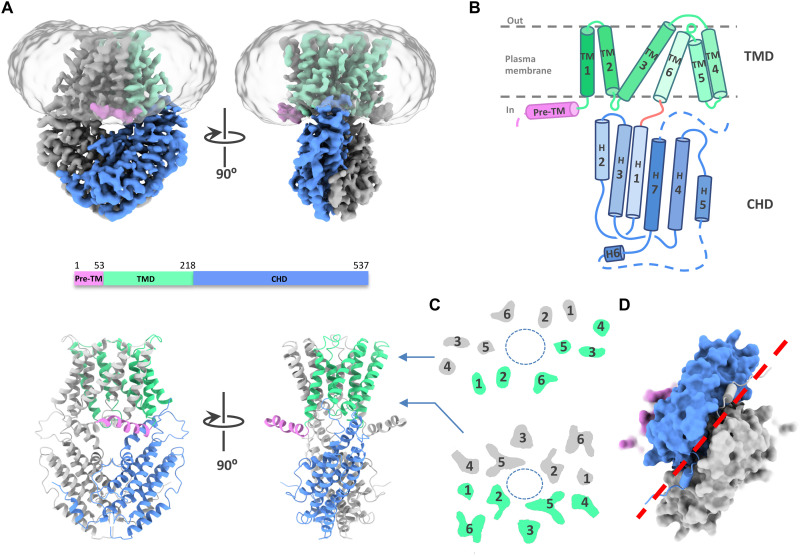
Fig. 1. Architecture of the GmALMT12/QUAC1 channel.
(A) Overall structure of the GmALMT12/QUAC1 channel. The cryo-EM density maps (top) and ribbon drawings (bottom) are shown, with the pre-TM helix in pink, TMD in green, and CHD in blue in one protomer. Another protomer is colored in gray. (B) Topology of the GmALMT12/QUAC1 protomer. The six helices in TMD are marked by TM1 to TM6, and the seven helices in CHD are marked as H1 to H7. The membrane boundary is shown as gray lines. The disordered regions are indicated as dashed lines. (C) Top view of the cross section of the transmembrane layer at the indicated positions by the arrow lines in (A). The elliptical dashed line marks the pore, and the TMs are indicated. (D) Bottom view of the C-terminal dimeric domains, colored as in (A). The domain-swapped finger helix H6 is shown as cylinder cartoon, and a red dashed line marks the dimeric interface of the CHD.

