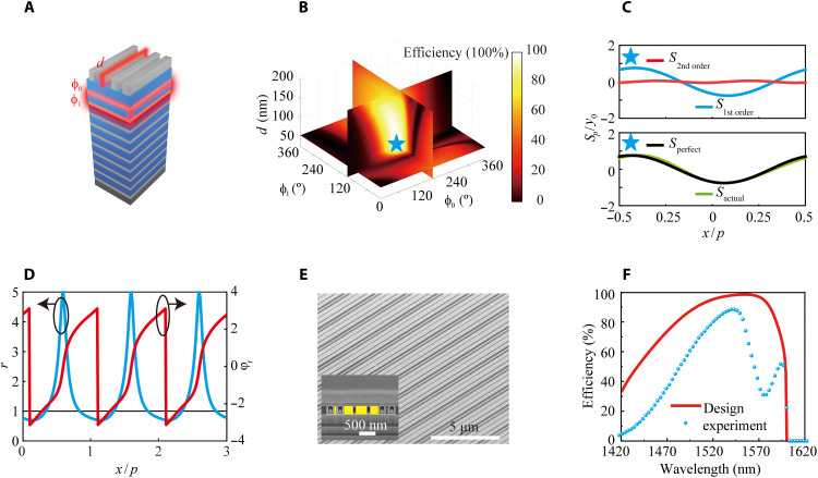
Fig. 4. Design and analysis of 75° perfect anomalous reflection.
(A) The width of the second grating, ϕ0, and ϕ1 are selected for scanning to realize perfect anomalous reflection at 75°. The geometric parameters of the final four elements are listed. The height of the six elements is 315 nm, and the widths are 174, 64, 264, and 370 nm. (B) Anomalous reflection efficiency versus the three parameters. The parameters for perfect anomalous reflection are marked by a blue pentagram. The exact parameters for d, ϕ0, and ϕ1 are 64 nm, 170°, and 149°, respectively. (C) Comparison of the actual energy flow distribution and distribution corresponding to perfect anomalous reflection at 75°. (D) Actual reflection coefficients of the whole metasystem, including the amplitude r(x) and reflection phase φr(x). (E) SEM side view image and cross-sectional image of the sample. The holes in the SEM image come from the insufficient deposition in the focused ion beam process. (F) Broadband efficiency measured in the experiment and calculated in the design.

