
Fig. 1.
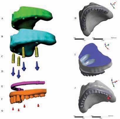
Three dimensional model, geometries, boundary conditions, and loading configuration in finite element analysis models (left: modeling/geometries). Cancellous bone ( A ), cortical bone ( B ), four morse-taper implants ( C ), four mini-conical abutments ( D ), bar ( E ), full-arch total prosthesis ( F ), four mini-conical abutment screws ( G ) (right: postprocessing). Mesh ( H ), boundary conditions ( I ), posterior load on left first molar ( J ).