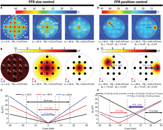
Figure 6.

Focused heating of MNP. Thermal images A), simulated FFR B), and magnetic field distribution along the X‐axis C) when applying an FFR with different magnetic field gradient ∇Br values. Thermal images D), simulated FFR E), and magnetic field distribution along the X‐axis F) when shifting the position of the FFR for ∇Br = 0.65 mT mm−1.
