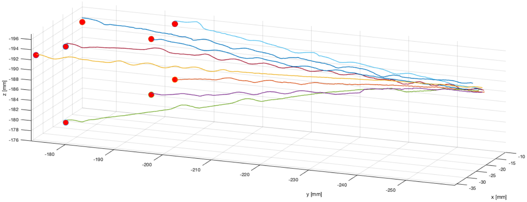
Figure 5.

Benchtop needle steering experimental needle tip paths, as measured by the magnetic tracker embedded in the needle’s tip. The target points selected in magnetic tracker space are indicated by red spheres. Data points in the traces above are spaced approximately 78μm from one another, and 25-point moving average was used to filter sensor noise prior to plotting. The slight wobbles in the traces indicate times when the closed loop controller re-oriented the flexure-tip needle (the tip of the bevel is plotted).
