Figure 9.

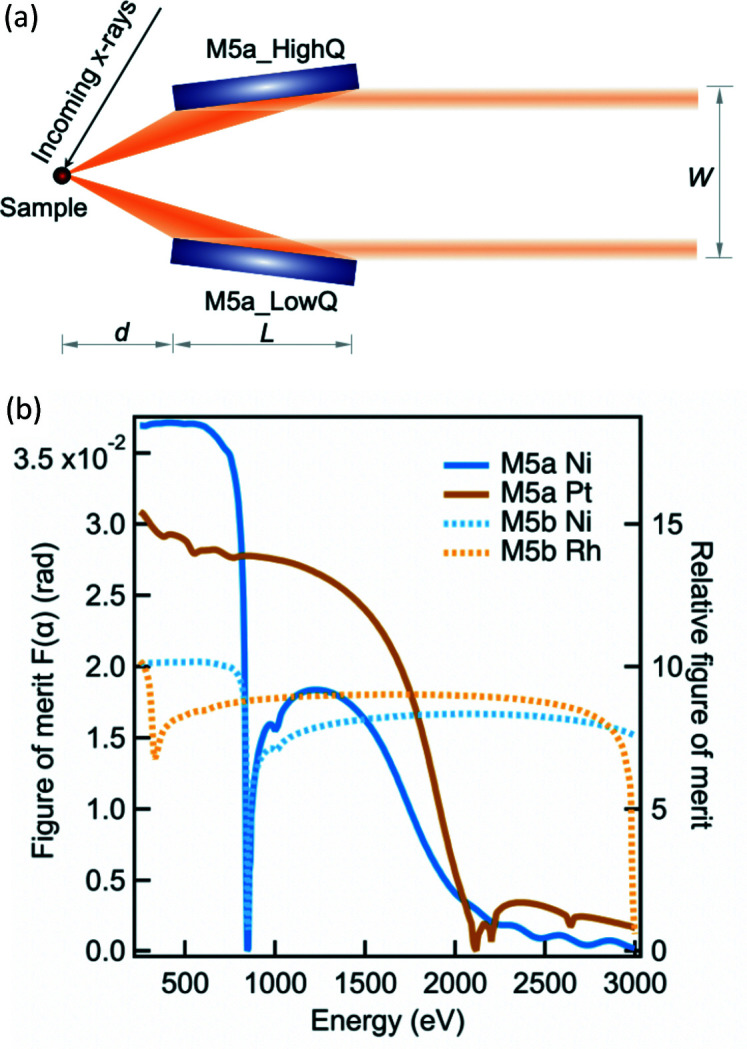
(a) Schematic top view of the M5a optics layout. d, L and W are equal to 55 mm, 190 mm and 30 mm, respectively, as optimized for the I21 beamline. (b) The simulated figure of merit of both M5a and M5b mirrors as a function of energy.

(a) Schematic top view of the M5a optics layout. d, L and W are equal to 55 mm, 190 mm and 30 mm, respectively, as optimized for the I21 beamline. (b) The simulated figure of merit of both M5a and M5b mirrors as a function of energy.