
Figure 2.
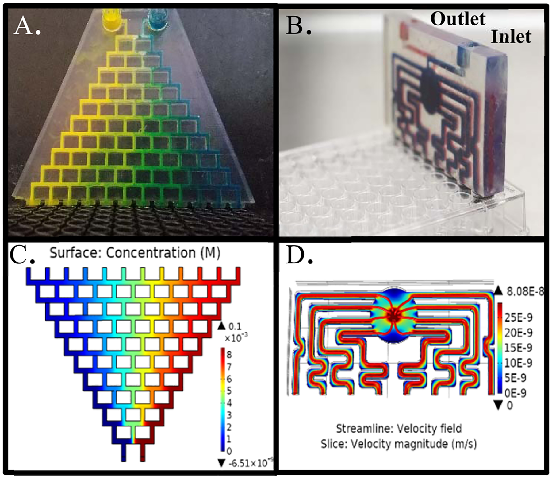
Device components: gradient generator and distribution networks. (A) Photograph of the gradient generator injected with artificial coloring (food dye) to demonstrate mixing. (B). Blue and red dyes are used to denote mirror image inlet and outlet channels, respectively. Outlet channels (red) are located parallel to, and directly behind, inlet channels (blue). (C) COMSOL simulation of gradient generator displaying 12 unique concentrations and (D) COMSOL simulation of distribution network displaying equal distribution of flow rate streamlines (red) and surface velocity (color map).