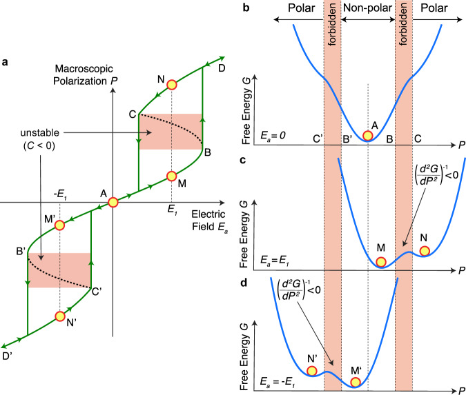
Fig. 1. Origin of antiferroelectric negative capacitance.
a The polarization P-electric field Ea characteristics of an antiferroelectric material. The segment BAB’ corresponds to the non-polar, antiferroelectric ground state, and segments CD and C’D’ correspond to the polar phase. Segments BC and B’C’ represent the unstable negative capacitance (C < 0) regions. At Ea = E1, the antiferroelectric has two stable states: M and N. b–d The antiferroelectric free energy landscape at Ea = 0 (b), E1 (c) and −E1 (d). d2G/dP2 < 0 in the P-range corresponding to BC and B’C ‘forbidden’ regions.

