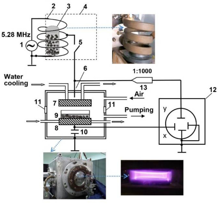
Figure 6.
Schematic diagram of the experimental setup: 1—RF generator, 2—inductor (the view right), 3—dielectric container with seeds, 4—screen, 5—commutator, 6—vacuum chamber (the view is shown below), 7—powered electrode, 8—lower electrode, 9—Petri dish with seeds, 10—measuring capacitor, 11—window (the view of ignited plasma is shown below right), 12—oscilloscope, 13—voltage probe.

