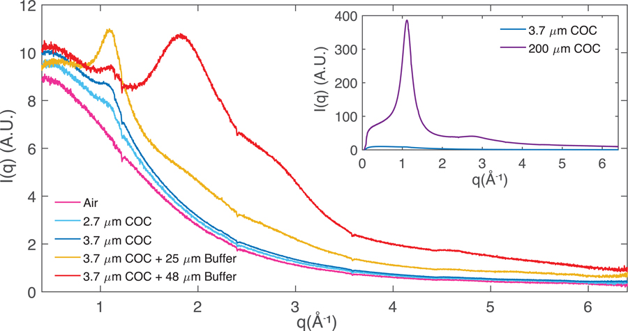
Figure 5:
Radial averages of scattering associated with crystal-free chips (or instrument-associated air scattering) to quantify background scattering contributions. Air (cyan, blue) and buffer-filled (red, yellow) chips with nominal 2.7 μm (cyan) or 3.7 μm (yellow, blue, red) COC enclosing films and 50 μm (red) or 25 μm (yellow) spacer layers are shown. Note: The data represented by the yellow curve, collected during a separate beamtime using a different batch of COC material from Polysciences Inc., shows a slightly different scatter profile at low q. Inset: Comparison of scattering intensity from the 200 μm COC support frame material and a 3.7 μm enclosing film.

