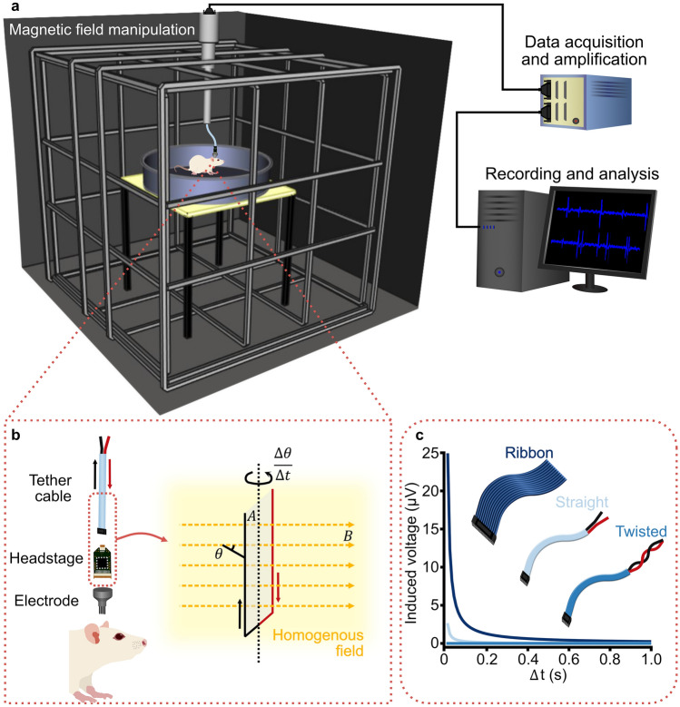
Fig. 1.
Schematic illustration of in vivo tetrode recordings in a freely moving rat during a magnetic field manipulation study. a Rat in a 1 m diameter circular arena placed in the centre of a 2 m × 2 m × 2 m triple-wrapped 3D Merritt coil system, which gives a 99% homogeneous field of 1 m diameter. Thus, the entire behavioural arena is within the homogeneous magnetic field. The 3D Merritt coil system allows a magnetic field of any azimuth or inclination to be produced. A tether cable connects the tetrode headstage on the rat to a commutator, with only the length of cable within the homogeneous area movable (~ 0.5 m). A cable from the commutator runs outside the electrically shielded room to a data acquisition box for amplification and filtering, before sending the signal to a computer for recording, processing and analysis. b Within the tether cable (red wire: voltage supply to the operational amplifiers in the headstage; black wire: the signal lines), the amplitude of the induced voltage in the largest conductive loop is a function of the enclosed area () of the loop, the magnetic field (; yellow dashed arrows) in the homogeneous field (yellow shading), and the angular velocity . c Example plot of induced voltage as a function of the enclosed area of the loop, demonstrated by three cable types – ribbon, straight bundle and twisted pairs. For all three examples, the length of the cable is set to 0.5 m, the rotation () is set to 90 degrees and the magnetic field intensity () to 50 µT. The rotation time ( increases to 1 s. The distance between the voltage supply and signal wires is set to ribbon = 1 cm, straight bundle = 1 mm and twisted wire = 0 mm

