Fig. 3.
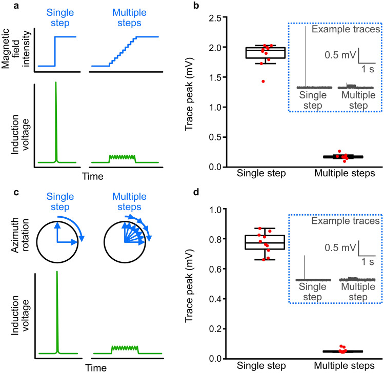
Induction artefacts cause by discrete vs gradual changes in magnetic field. a Schematic illustration of induction artefacts caused by a large, discrete change in magnetic field intensity, compared to a gradual change. b Peak induction voltages measured in a 2 m tether wire, placed within a magnetic coil system, resulting from turning the magnetic field from 0 to 50 µT, either immediately or at a rate of 100 µT/s. Trace peaks (inset: example traces) were significantly smaller when the magnetic field was gradually increased, compared to being increased in a single, discrete, step (two-sided t test; t(18) = 28.31, p < 0.0001). c Schematic illustration of induction artefacts caused by a large, discrete change in magnetic field azimuth, compared to a gradual change. d Peak induction voltages measured during a magnetic field rotation of 90°, either immediately or at a field vector rate of 100 µT/s (~ 180 degrees/s). Trace peaks (inset: example traces) were significantly smaller when the magnetic field was gradually rotated, compared to being rotated in a single, discrete, step (two-sided t test; t(18) = 31.18, p < 0.0001)

