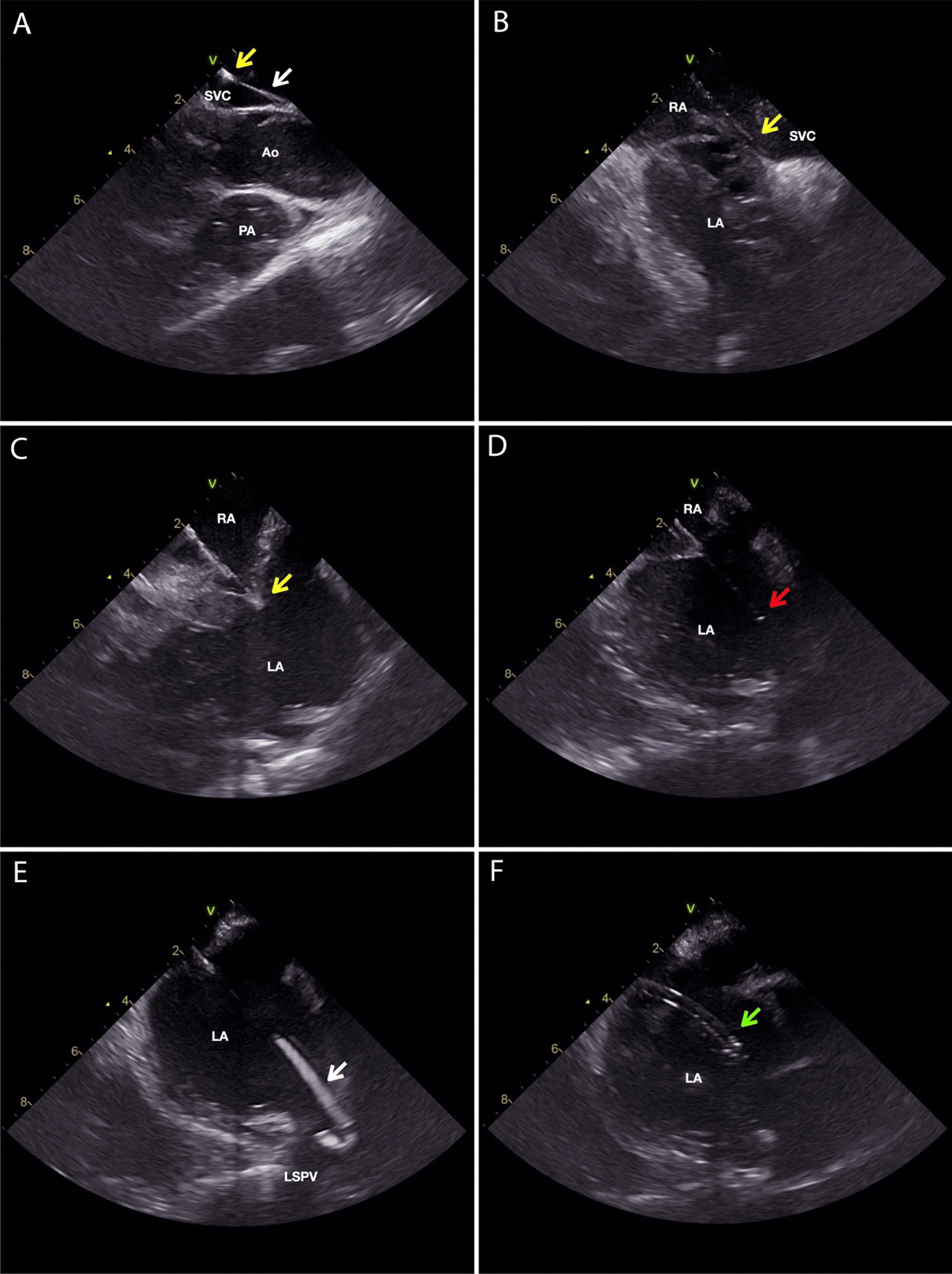
Fig. 1.

ICE images of the zero fluoroscopy transseptal puncture guided by ICE only. Guide wire is marked with a white arrow, the tip of the dilator is marked with a yellow arrow, the tip of the transseptal needle is marked with a red arrow, and the tip of the long sheath is marked with a green arrow. A The guide wire is advanced through the SVC and the long sheath with a dilator fully inserted is advanced over the guide wire into the SVC. The ICE probe is located in the SVC just above the RA and SVC junction. B The guide wire is removed and the transseptal needle is not fully inserted into the long sheath with 1–2 cm of the needle outside the sheath. The long sheath / dilator / transseptal needle assembly is pulled down from the SVC to the interatrial septum. C The tip of the dilator is positioned on the oval fossa. At this moment, a tenting of the interatrial septum can be observed. D the needle is pushed fully into the long sheath. Transseptal puncture is performed. E the transseptal needle is withdrawn and the guidewire is advanced through the dilator into the LSPV. F the guide wire and the dilator are withdrawn with the tip of the long sheath in the LA. Ao—aorta; LA—left atrium; LSPV—left superior pulmonary vein; PA—pulmonary artery; RA—right atrium; SVC—superior vena cava
