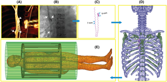
FIGURE 1.

Steps of image segmentation and fragmented retained lead (FRL) model construction. (A–C) Computed tomography images were used to extract the 3D trajectory of FRL, whereas X‐ray images were used to reconstruct the FRL’s structure (e.g., number and pitch of loops). White arrows show the FRL on each image. (D) A triangulated surface of patient’s ribcage (green) was created and aligned with the ANSYS multicompartment body model (blue) to position the patient‐derived FRL model inside the ANSYS human body model. (E) Body model positioned inside the MRI coil
